“CHROME CARBIDE OVERLAY PLATE”
(IT’S NOT ALL THE SAME)
By
Bob Miller
Bob Miller is a metallurgist and wear consultant with Clad Technologies, Birmingham, Alabama 205-978-5186
Introduction
30 years ago, Chrome Carbide Overlay Plate was being manufactured by a relatively few firms. Because of it’s immense popularity and versatility for severe abrasion applications the field of manufactures has become more populated. As with most advancing technologies, variations in manufacturing methods tend to influence the finished product. The consumer, in all probability, assumes that the “chrome carbide plate” is generically all the same. This paper attempts to dispel that notion by describing the various methods of overlay plate manufacturing and their affects upon the quality, consistency and wear properties of the final product.
The Basic Product
Chrome Carbide Overlay Plate consists of a mild steel base plate onto which a highly abrasive resistant welded overlay is deposited using an open arc or submerged arc process. Plate sizes typically range from 3/8″ to 1-1/2″ in thickness; widths vary from 4′ to 8′ and lengths from 8′ to 20′. The overlay deposit is either one or two layers, measuring 1/4″ or 3/8″ thick. Bead widths vary according to the method of manufacture but typically measure about 1-1/2″ wide and are randomly check cracked. Check cracking occurs as a natural phenomenon during welding and is controlled by the chemical composition of the overlay or by cooling methods. Overlay deposit chemistry ranges from 15% to 30% Chromium, 3.0% to 4.5% Carbon. Manganese, and Silicon may vary from 1% to 4% each. Molybdenum may exist up to 3%. Deposit hardness varies from 400 BHN to 600 BHN, and is typically 550 BHN to 600 BHN. The finished plates can be formed and fabricated. Holes can be cut with either plasma or electro discharge machining (EDM) techniques.
Hardness, Chemistry & Wear
A material’s hardness has long been erroneously used as a criteria for wear resistance. This can be demonstrated by comparing the wear resistance of an alloy steel with a white iron, both having hardness values of 550 BHN. ASTM G65 wear test results consistently show a marked superiority in wear resistance of the white iron.
Material | Hardness | C | Cr | Mo | G65 |
Alloy Steel | 550 | 0.50 | 3.50 | 0.50 | 1.40 |
White Iron | 550 | 4.50 | 20.0 | 2.0 | 0.22 |
Mild Steel | 90 | 0.25 | 0.00 | 0.00 | 2.51 |
C=Carbon Cr=Chromium Mo=Molybdenum
The reason for such a disparity in wear resistance despite the two materials having identical hardness values, lies in the hardness test itself. Popular hardness test devices, such as Brinnel and Rockwell measure a materials macro hardness. Each metallurgical component of the material has it’s own microhardness which then contributes to the macrohardness. The Alloy Steel, has a predominately single metallurgical component, (Martensite) and it’s microhardness is nearly identical to the macrohardness. The White Iron has a dual metallurgical structure, consisting of Chrome Carbide, with a very high microhardness, embedded in Austenite, with a very low microhardness. The resulting Brinell macrohardness value (550 BHN) is really an average of the two microhardness values. Hardness values only become relevant when comparisons are made within a family of steels, and this can be misleading at times. It is best therefore to dismiss any relationship between hardness and wear resistance. Actual chemical compositions and resulting metallurgical structures should be considered as criteria. The results of these considerations are manifested not in the hardness test but in the actual wear test such as ASTM G 65.
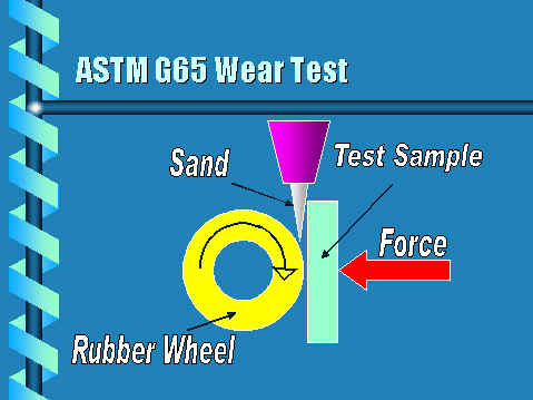
Wear Testing – ASTM G65
There are a number of different types of wear. Low stress or scratching abrasion is probably the most predominate in the mining industry. A quantitative method of measuring a material’s resistance to this scratching type abrasion is the Dry Sand Rubber Wheel Test, or ASTM G65. This test characterizes materials in terms of weight loss under a controlled set of laboratory conditions. Correlation to actual field conditions may be influenced by other wear parameters such as the amount of impact, corrosion, galling, etc. Nevertheless, valuable insight into a materials field performance may be gained by examining the results of this test against a material’s chemistry and microstructure. This then is the criteria in which all materials used in abrasive wear applications should be subjected.
Methods of Manufacture
Various methods of manufacture have evolved over the years since the introduction of Chrome Carbide overlay plate. Currently, all popular manufacturing methods can be characterized as follows:
- Arc Welding Process Used
- Open Arc
- Submerged Arc or Fusion Bond Welding
- Base Plate Configuration Used
- Flat Plate or Table Design
- Cylindrical Drum
The selection of any of these variables can have a profound affect upon the quality, consistency, integrity and wear properties of the plate. An examination of each variable is described below.
Arc Welding Process
Two basic welding processes are used in the manufacturing of cladded plate; open arc and submerged are. Each has its features and limitations. The consumer should be aware of the welding process used because of the direct correlation between welding process and wear resistance as will be shown But before a serious evaluation can be made, there are a few items that need clarification:
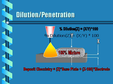
- All arc welding deposits consist of a mixture of the wire composition and base metal composition. The amount of this mixing is expressed as a dilution percentage. In other words, a 30% dilution factor for a welding process means that the resulting weld deposit consists of 30% base metal and 70% wire.
- The arc welding deposits as discussed above are thoroughly mixed. There is no visual division of either the base metal component or the wire component. It is a complete and homogeneous
Open Arc Welding:
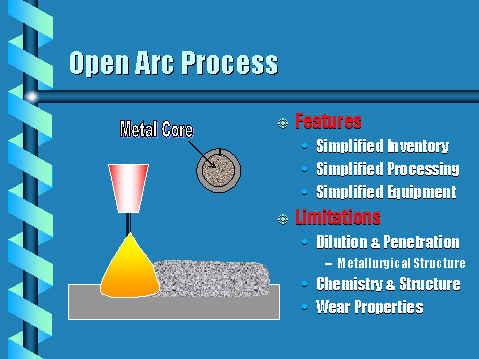
Open arc welding is accomplished with a cored wire of the proper diameter. No gas or flux is added to the process. All the slag, flux, gas cover, and alloys are included within the core of the tube. The wire is fabricated from a low carbon strip and the critical ingredients are added during the fabrication. The wire is then packaged for shipment in 500 Lb. containers for consumption. Since this is the only welding consumable used in the plate manufacturing, inventories are relatively simple. Process control is also quite simple since only standard arc voltages, currents and wire feed rates require attention. Deposits are relatively smooth, but are susceptible to roughness and poor tie-in between the weld beads. The most severe limitation of the open arc welding process is its inability to produce chemical compositions acceptable for maximum wear resistance in the first layer. This inadequacy can be traced back to a combination of wire fabrication and process variables. The fabricated tube consists of a hole that will accept only a certain amount of alloy. In this case, about 30% Chromium and 5% Carbon plus other key ingredients. This is compounded by the fact that the open arc process inherently produces about 40% dilution. This equates to a deposit chemical composition of about 18% Chromium and 3.0% Carbon. It has been demonstrated through ASTM G65 abrasion tests that a minimum of 20% Chromium and 4% Carbon is required for acceptable wear. Second layers are also subject to the effects of dilution but to a lesser extent. Under the above criteria, second layer will consist of 25.2% Cr and 4.2% Carbon. This is sufficient for acceptable wear.
From the data above, it becomes apparent that the Sub Arc deposits are superior in wear resistance to Open Arc deposits.
Submerged Arc / Fusion Bond Welding:
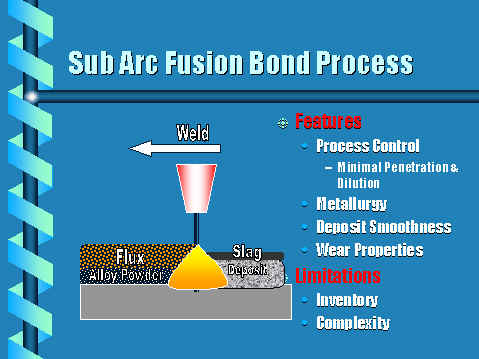
Submerged Arc Welding is accomplished through the use of a solid or cored wire and added flux. The arc melts both the wire and the flux and forms a weld bead and an easily removable slag covering. Dilution factors are typically 30/40%. Fusion Bond Welding is also a submerged arc process but with the addition of alloy powder. The addition of powder greatly reduces the dilution to about 10%. By over alloying with alloy powder the 10% dilution factor can be overcome. Thus it is possible to deposit a chemical composition of 30% Chromium and over 4.0% Carbon within the first layer. This composition is quite acceptable from a wear standpoint.
Additional features included in the Fusion Bond Welding process are; smooth deposits with extremely shallow peaks and valleys, process control, deposit consistency . The major limitation is the inventorying of three welding consumables; wire, flux and alloy powder. However, it is the flexibility of arc welding process and deposit chemistry control that far outweigh this shortcoming.
Condition | Dilution (%) | C | Cr | G65 (Wt. Loss) |
Open Arc Wire | 5.00 | 30.0 | ||
Open Arc 1st Layer | 40% | 3.00 | 18.0 | 1.25 |
Open Arc 2nd Layer | 40% | 4.20 | 25.2 | 0.40 |
Sub Arc 1st Layer | 10% | 4.30 | 28.0 | 0.33 |
Sub Arc 2nd Layer | 10% | 4.55 | 30.0 | 0.19 |
Mild Steel 1020 Steel | 2.51 |
Base Plate Configuration
A36 or 1020 flat steel plate of various sizes is procured for overlay. The manufacturer has two options in configuring the plate for the overlay process; (1) use the flat plate as it was purchased and place the plate on a specially designed flat table, (2) roll the flat plate into a cylinder, seam weld, and place it on a specially designed horizontal turning device for the overlay process. Each has its features and limitations and the choice made by the manufacturer has consequences that affect the overall quality and integrity of the end product. A description of each follows.
Table Method:
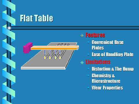
The obvious advantage with this configuration is the ease of plate handling. Since the plate is purchased as flat plate, it makes good sense to just place it on the table and overlay with either an open arc or Fusion Bond welding process. Once the overlay is complete, the plate is then subjected to a straightening or flattening process and then trimmed to size on a plasma cutting table. The process is quite simple and straight forward. However, serious complications often arise during the welding of base plates of less than 3/4″ thick. Distortions, in the form of large humps, plague the process and compromise deposit integrity Each time a hump is encountered by the welding arc, penetration and dilution of the base plate is increased. This means that the chemistry of the humped region could become unacceptable for maximum wear. The economics of the table approach are quite attractive from a manufacturing standpoint.
Drum Method:
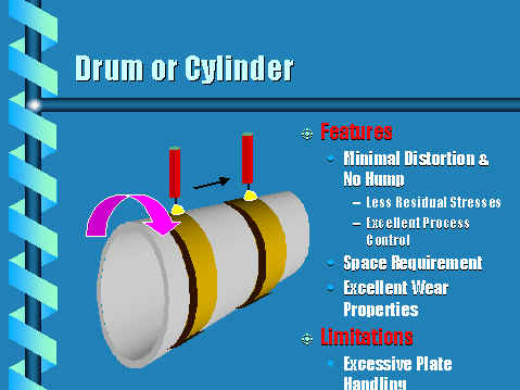
The obvious drawback to this approach to manufacturing overlay plate is the excessive handling and working of the plate. It must first be rolled into a cylinder, seam welded and then placed on the tuning device for overlay. After the overlay process is complete, the drum must then be plasma cut along the seam and rolled flat prior to plasma trimming. Despite this limitation, the drum method has a very redeeming attribute; i.e. the lack of distortion. No humps occur during welding and any dimensional changes that do occur are easily accommodated by adjusting the turning fixture. Process control is optimized. Chemical composition and wear properties are consistent throughout the plate.
The options for manufacturing overlay plate are varied and the final choice may depend upon the availability of raw material, manufacturing space, and of course economic considerations. Clearly the final product is predicated upon the mode of manufacture. The consumer of overlay plate may seem somewhat bewildered at these manufacturing variables. The following chart was devised to help guide the consumer in making a choice of an overlay plate vendor. Each feature has been rated on a scale of 1 to 10, ( “10” being the most desirable and “1” being the least desirable).
Feature | Open Arc Weld | Sub Arc Fusion Bond | Flat Table | Drum |
Distortion | 8 | 10 | 7 | 10 |
Mircro- Structure | 7 | 10 | 7 | 10 |
Process Control | 7 | 10 | 8 | 10 |
Inventory | 10 | 7 | N/A | NA |
Wear Properties | 8 | 10 | 8 | 10 |
Cost Effective | 9 | 10 | 9 | 8 |
Process Complexity | 10 | 7 | 10 | 8 |
Total | 59 | 64 | 49 | 56 |
Conclusion
Various methods of overlay plate manufacturing have been identified and evaluated. Each has its own features and limitations. As technology advances, other processing methods will be introduced and their success will ultimately be dictated by the consumer’s acceptance. The existing methods will no doubt go through the growing pains of improvement where it is warranted. The consumer, however, has only the present to deal with. Armed with the information this article has outlined, the consumer now has another tool in which to intelligently discriminate among overlay plate suppliers. A simple check off list might be helpful.
- Welding Method
- Sub Arc Bulk Welding
- Open Arc
- Other
- Plate Configuration
- Flat Table
- Cylindrical Drum
- In House Wear Testing
- ASTM G65
- Outside Source
- Other
- Quality Control Method
- Wire Chemistry
- Deposit Chemistry
- Hardness
- Wear Test
- None
- Frequency of Testing
- Each Plate
- Periodically
- Upon Request
- Not Available
- Certification
- Specifications
- Actual Test Results
- Sizes
- Thickness, Lengths, Widths
- Cladding Thickness
- Availability
- Days
- Weeks
- Months
- Welding Method
Reprinted Articles courtesy of cladtechnologies.com