Submerged Arc Welding
call us today
- 1-800-567-1362
Identification of Cracks in Weld Sections
Cracks are probably the worst of all welding defects that can be found in a welded joint as they can start small but grow over time. Cracks can be found in just about every type of weld, solder, or braze joint, and in practically every location including the bond region, HAZ (Heat Affected Zone), and parent metal. There are multiple tools available for detecting cracks including non-destructive techniques such as ultrasound, x-ray, and CT scans; but those techniques are not always applicable for a particular joint design or can be quite expensive for frequent use. The most commonly used technique for detecting crack is a metallographic evaluation of the weld. But that technique has its own problems which makes cracks difficult to detect for multiple reasons which is the focus of this newsletter. The first is the effect of sample preparation process that can smear material into or over the crack. Smearing is a common problem, especially in soft alloys such as copper and aluminum; polishing of soft alloys requires practice and is not a trivial operation. Polishing of soft alloys does require mounting the samples with epoxy so that they can be held on fixed plane during polish; polishing has to be performed in gradual decreasing increments of sandpapers grades and then with colloidal ceramic powders such as alumina and diamond. Careful polishing is essential to ensure there is no smearing on the surface where material can get pushed around and ends up smothering the crack. The second reason it is difficult to detect cracks as their appearance is not always like a straight line as is show in schematics but can meander around grain boundaries making it difficult to differentiate between the two. In the absence of any stress trying to open up the crack, the crack width can be very fine and sometimes indistinguishable from grain boundary. The third reason cracks are difficult to identify is that the metallographic section is a 2-dimensional cut, while the actual crack may have 3- dimensional profile which is only partially captured the plane of sectioning. If you suspect that the crack is bigger than it appears, one option is to keep polishing the section down and track the crack along the z-direction. Cracks can sometimes have path or plane which is aligned to a specific orientation as relates to the joint or applied stress and perhaps you may have to section multiple samples along different planes to get a good understanding on the crack morphology. The final and often the main reason for difficulty in identifying cracks is due to the lack of sufficient contrast in metallographic sections that are often etched before review. Since cracks will often resemble features in a metallograph such as a long grain boundary or a boundary between two phases, some of the finer cracks may be missed altogether. Hence, I recommend that metallographic sections be photographed twice; first after fine polishing, and then, after etching. A photograph of an unetched but finely polished section will provide sufficient contrast for positive identification of a crack. Comparison of the un-etched and etched photographs will help identify location and potential reasons for crack formation
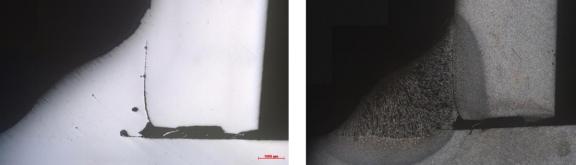
Figure 1 above shows an arc weld before (left) and after (right) etching. The crack, which in this case is a line showing lack of fusion is clearly evident in the unetched section but not so obvious in the etched section.
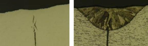
Figure 2 above shows a laser weld section in similar situation where the crack is more obvious in the un-etched section on the left but not so in the etched section on the right.
Reprinted Articles courtesy of cladtechnologies.com & fabricator.com
Cladded Wear Plates in Mining Applications
Hardfacing in your everyday life
We Manufacture:
All of our welding tips are made from the highest quality ISO Extruded Tubing.
Schedule Your FREE Trial
in North America
Superior Consumables product is backed by proven, documented test results.
For All Your Mig Welding Needs!